Pulsation (Acoustic) Analysis
Pulsation (Acoustic) Analysis
Modeling Capabilities
The capabilities of EDI’s pulsation analysis software include:
-
Simulation of simultaneous operation of parallel compressors or pumps
-
Simulation of simultaneous operation of all stages of compressors
-
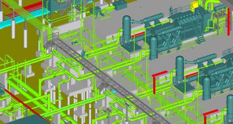
Modeling of complex piping systems of virtually unlimited size
-
Time Domain simulation
-
Frequency Domain simulation
-
Hydrocom Valve capabilities
-
Time Domain Valve Dynamics simulation
- Evaluation of Dynamic Power Loss (HP) across pressure drop elements (Note dynamic pressure drop is not an indication of power loss)
Design Philosophy
EDI’s philosophy for vibration control puts emphasis on robust pulsation control. This philosophy optimizes pulsation control using acoustical filtering or properly sized surge volumes where applicable, to eliminate excessive pulsation induced forces rather than emphasizing unreliable “brute force” mechanical restraint alone. This design philosophy is the “default” of API 618.
API 618 for Reciprocating Compressors
Fourth Edition
API has established standard guidelines for reciprocating compressors in API Standard 618. The previous version of the standard is the Fourth Edition, adopted in June 1995. The Fifth Edition was issued in 2007, however the Fourth Edition is still often used as a basis for many studies.
The Fourth Edition of API 618 establishes requirements for pulsation and vibration control of reciprocating compressors. Section 3.9 outlines three design approaches:
- Design Approach 1: Simplified analysis without acoustical simulation.
- Design Approach 2: Acoustical/mechanical analysis of piping system, including the use of proven acoustical suppression devices, with piping restraint analysis.
- Design Approach 3: Same as Design Approach 2, but including a mechanical analysis of the compressor manifold system.
Appendix M of API 618 Fourth Edition lists procedures corresponding to each design approach.
-
M.1 Analytical Study: Same as Design Approach 1.
Design Approach 2:
- M.2 Acoustical Analysis (Acoustical Simulation Study): Part of Design Approaches 2 and 3.
- M.3 Performance Analysis (Pulsation and Pressure Drop Effects): Part of Design Approaches 2 and 3.
- M.4 Piping System: Part of Design Approaches 2 and 3.
Design Approach 3 Adds:
- M.5 Compressor Manifold System Mechanical Natural Frequency Analysis.
- M.6 Compressor Manifold System Vibration and Dynamic Stress Analysis.
- M.7 Piping System Dynamic Stress Analysis.
- M.8 Calculation of Dynamic and Static Stresses on Pulsation Suppressor Internals.
M.6, M.7 and M.8 are often considered as options.
Design Approach 3 Options:
- M.9 Compressor Valve Dynamic Response Study.
- M.10 Pulsation Suppression Device Low Cycle Fatigue Analysis.
- M.11 Piping System Flexibility.
For most systems, it is sufficient to perform procedures M.2 – M.5. If the design procedures involved in M.2 – M.5 are carried out properly, it is EDI’s experience that the additional analyses (M.6 – M.10) are not necessary. Proper application of procedures M.2 – M.5 results in robust pulsation and vibration control.
Fifth Edition
The Fifth Edition specifies analyses equivalent to the Fourth Edition. However, forced vibration (equivalent to M.6 and M.7 of Fourth Edition), are not required if certain requirements are met. Three design approaches, Approach 1, 2 and 3, are also used in the Fifth Edition.
-
Design Approach 1: Empirical Pulsation Suppression Device Sizing.
-
Design Approach 2: Acoustic Simulation and Piping Restraint Analysis.
-
Design Approach 3: Acoustic Simulation and Piping Restraint Analysis plus Mechanical Analysis (with Forced Mechanical Response Analysis if necessary).
-
Step 3a: Mechanical Natural Frequency Analysis of the Compressor and Piping System to Avoid Coincidence with Significant Shaking Forces.
-
Step 3b1: Forced Mechanical Response Analysis of the Compressor Manifold System.
-
Step 3b2: Forced Mechanical Response of the Piping System.
Step 3b1 and 3b2 should not be depended upon as basis for justifying a design. These procedures are subject to modeling details which can cause significant inaccuracies in the results and improper conclusions regarding the design.

