To model entire rotor systems, the shaft dimensions, added weights and inertias, bearings, support stiffness, and seals need to be considered.
Shafts
The shaft cross-sectional inertial and mass properties are calculated from the length, outer diameter, and inner diameter of each shaft section from the shaft drawing. Rotating elements such as wheels and impellers are modeled as added masses and inertias at the appropriate locations on the shaft. The polar and transverse mass moments of inertia are included in the analyses to simulate the gyroscopic effects. The gyroscopic effects are particularly significant on overhung rotors where the impeller or disc produces a restoring moment when whirling in a deflected position.
Couplings are simulated as concentrated added weights and inertias. Normally the half-coupling weight is placed at the center of gravity of the half coupling. For most turbomachinery systems, flexible couplings effectively isolate the lateral vibrations of adjacent rotors. Therefore, each rotor can usually be analyzed independent of the coupled rotors. However, if the couplings do not isolate the rotors, the entire train, including the driver and driven equipment, should be modeled.
Bearings
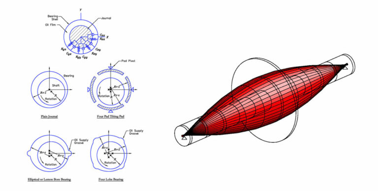
Hydrodynamic bearings create pressurized fluid films that support the shaft. These fluid films have stiffness, damping and mass effects that affect the rotordynamics of the supported shaft. These effects change with speed and are sometimes cross-coupled meaning shaft movement in one direction causes forces in another.
Various bearing designs are available to the manufacturers who then tailor the geometry to produce the stiffness and damping characteristics for a specific application. EDI uses several programs to calculate the stiffness, damping and mass coefficients for a variety of bearing designs. This is done over a range of loading and speed. Our engineers can then evaluate the rotordynamics of the machine and determine if a change to the bearing design is needed.
Seals
Seals used in centrifugal pumps and compressors experience high axial flow due to the pressure differential between stages. This flow results in a fluid film with stiffness, damping and mass effects just as with bearings although their effect is smaller. EDI calculates these coefficients for a range of loading and speed. Labyrinth tooth seals can also be analyzed.