Case Studies
Balancing of Forced Draft Fan
Problem
This a case study of a forced draft (FD) fan that experienced high vibration due to unbalance and an impeller resonance near the operating speed. The common balancing method of influence coefficients was unsuccessful due to varying phase data. However, vibration was reduced to an acceptable level using the four-run method without phase data.
The FD fan supplies air for a boiler and was driven by a steam turbine through a speed-reducing gearbox as shown Figure 1.
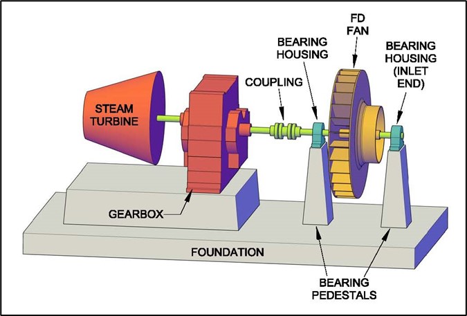
Figure 1
Refinery personnel reported high vibration several days after replacing the fan roller bearings. To reduce the vibration, a second set of replacement bearings was installed; however, the vibration remained high. Initial vibration data were acquired with a hand-held analyzer. The predominant vibration was in the horizontal direction and occurred at 1× running speed of 1745 RPM (29 Hz) of the fan.
During the inspection of the fan, five balance weights of various sizes were found already welded around the periphery of the impeller. This indicates previous trouble balancing the fan. The fan impeller was covered with a thin layer of dirt, so it was difficult to tell if a balance weight had possibly come loose.
There were no obvious signs of damage, and no foreign objects were found inside the fan housing. The amount of dirt would have been similar before and after the bearing replacements. Therefore, the inspection did not explain the change in vibration after installation of the new roller bearings. Other items to verify included: the speed rating of the roller bearings, bearing clearances, and proper lubrication.
Testing
High vibration at 1× running speed is a typical indication of unbalance. However, other factors can cause vibration problems as described in reference [1]. Therefore, the refinery requested that more detailed testing be performed before attempting to field balance the FD fan. The test procedure included the following steps:
- Measured operating deflection shape (ODS) while running at 1745 RPM with load.
- Monitored bearing housing vibration while reducing air flow to boiler.
- Maintenance personnel inspected fan while down.
- Performed impact tests of bearing pedestals and fan rotor.
- Created vibration waterfall and Bode plots during coastdown.
- Balanced fan using four-run balance method to reduce vibration.
- Final check of fan vibration with maximum air flow.
There are several commercially available software packages such as Clear Motion Systems that can be used to perform operating deflection shape (ODS) measurements. First, a simple wire-frame model was created from basic dimensions of the FD fan. The un-deformed representation of the bearing housings, bearing pedestals, and concrete foundation is shown in Figure 2 as dashed lines.
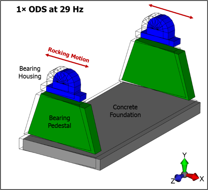
Figure 2
While operating the unit at constant speed and load, a tri-axial accelerometer was moved to 18 different locations to measure vibration in three orthogonal directions. Phase angles were determined from a stationary reference accelerometer. The software is then used to animate the measured vibration (amplitude and phase) at 1× running speed.
The highest vibration occurred at the top of the bearing housings in the horizontal direction. Figure 2 shows the rocking motion in which both ends (air inlet and coupling) were moving in-phase. The maximum vibration was approximately 6 mils p-p at 1× running speed (29 Hz). Vibration on the concrete foundation was 3 – 4 mils p-p, which was also considered excessive. However, no significant separation was found between bearing housings, pedestals, and concrete foundation. Therefore, looseness was ruled out as a possible cause of the high vibration.
As the fan was unloaded, the air flow reduced from 70,000 lb/hr to zero with the louvers closed, which caused the speed to increase from 1745 to 1760 RPM. During this time, the vibration levels of the fan bearings were monitored and no change in 1× vibration was observed. This demonstrated that the vibration was not caused by aerodynamic forces. Both bearings still had approximately the same level of vibration, which pointed to a static unbalance condition of the fan impeller and not coupling unbalance.
With the fan shutdown, impact tests were performed using an instrumented hammer containing a load cell. The results showed that the bearing housings did not have any natural frequencies near running speed. However, a natural frequency of the fan impeller was measured at 28 Hz and appeared to be more sensitive in the axial direction as shown in Figure 3. This natural frequency could be a wobble mode of the impeller, and could increase in frequency during operation due to gyroscopic effects. The EPRI paper by Smith [2] gives an example of a wobble mode.
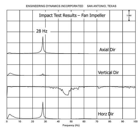
Figure 3
There is an insufficient separation margin between the 28 Hz natural frequency of the impeller and the operating speed of 29 Hz. For reliable operation, a separation margin of at least 10% is recommended. Therefore, the fan vibration could be amplified due to the resonant condition and the fan would be sensitive to even small amounts in unbalance. A change in unbalance condition could be caused by dirt build-up, a lost balance weight, or insufficient press fit of the impeller on the shaft allowing the impeller to shift slightly.
Vibration data were acquired during coastdown. Vibration waterfall (Figure 4) and Bode (Figure 5) plots showed that two peaks occurred during the coastdown. It was unknown if the second peak was caused by a sudden change in speed as the steam was cut off to the turbine or if this might be a critical speed of the fan. The phase shift confirmed a resonance. In addition, the vibration is amplified above the expected speed squared relationship due to pure unbalance.
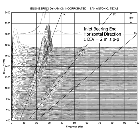
Figure 4
Figure 5
Balancing
During the inspection, previous balancing locations were found all around the fan impeller. This indicated trouble balancing the fan using the typical influence coefficient method. Because the fan was running near a resonance, the phase angles could vary significantly at slightly different operating speeds. It was difficult to hold the speed of the steam turbine constant.
The refinery was willing to start and stop the fan multiple times, so it was decided to try the four-run balance method. The four-run method is best for balancing near a resonance because it does not rely on phase data. Dennis Shreve discussed this simple balancing procedure in the previous issue of UPTIME Magazine [3], and it is also detailed in reference [1]. Therefore, the four-run procedure will not be repeated here.
To prepare for the four-run balance, the fan blades were numbered 0 to 11 (opposite direction of rotation). An optical tach and strobe light were used to ensure that all balance runs were performed at approximately the same speed of 1745 RPM. For the trial weight, a washer weighing 3.2 ounces was selected. A general rule of thumb for determining an appropriate trial weight is that the resulting unbalanced force should not exceed 10% of the rotor weight. Table 1 summarizes the vibration data.
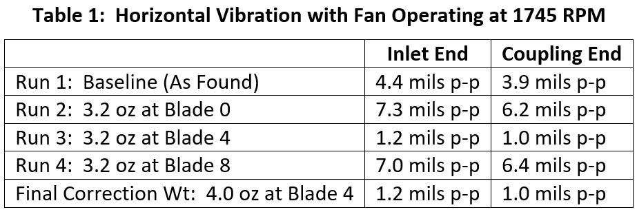
Since the vibration readings were slightly higher on the inlet end, these values were used to construct the diagram shown in Figure 6. The four-run balancing method uses circles to represent vibration amplitudes from each run. The approximate intersection point of the circles indicates the final balance weight location. For this case, 3.95 mils p-p @ 131 deg was near blade 4. The correction weight would then be 3.2 oz × 4.4 mils / 3.95 mils = 3.6 oz as noted in Figure 6.
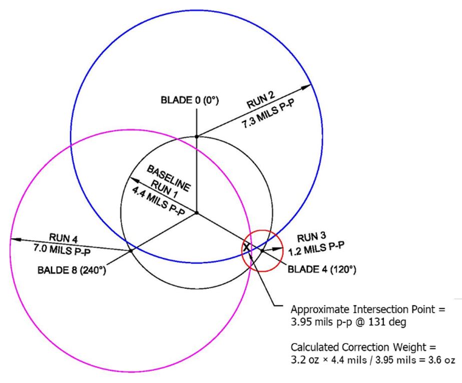
Figure 6. Four-Run Balancing Method
A weight of 4.0 ounces was tried at blade 4. As shown in Table 1, the vibration readings with the 4-oz weight were similar to Run 3. Therefore, it was decided to leave the 4-oz weight installed and to stop balancing since no further improvement was made. All of the vibration levels shown in Table 1 were for no load conditions. Figure 7 compares the “before and after” vibration readings while operating the fan at 1745-1750 RPM with full air flow.
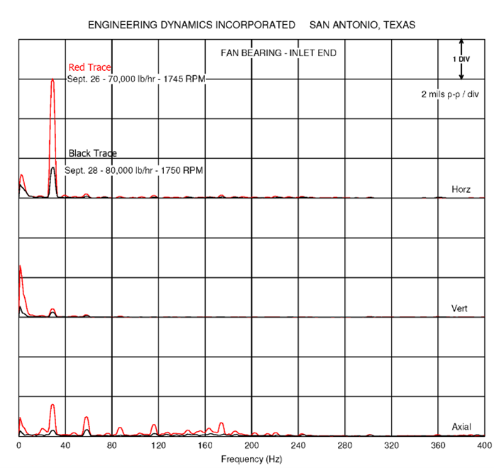
Figure 7
Conclusions
This case history demonstrates how the four-run balance method was used in a real-world application. If the fan would have continued operation with high vibration, the new roller bearings could have been damaged due to the excessive unbalanced forces. At the time of the field study, the fan was scheduled to be replaced in approximately one year. Therefore, the manager of the refinery was satisfied with the short-term solution of field balancing to reduce the fan vibration to an acceptable level.
With one or two natural frequencies near the operating speed, the fan was still very sensitive to small amounts of unbalance due to dirt build-up, etc. For long-term reliability, natural frequencies of the fan rotor, impeller, and foundation should have a separation margin of at least 10% from the operating speed range. The refinery maintenance department reports that this fan was always difficult to balance and has now been replaced with a new one, which is more reliable.
References
- Feese, T. D. and Grazier, P. E., “Balance This! Case Histories from Difficult Balancing Jobs,” 33rd Texas A&M Turbomachinery Symposium, Houston, Texas, September 2004.
- Smith, D. R. and Wachel, J. C., “Controlling Fan Vibration – Case Histories,” EPRI Symposium on Power Plant Fans: The State of the Art, Indianapolis, Indiana, October 1981.
- Shreve, Dennis, “Balancing Without Phase,” UPTIME Magazine, January 2011.