Case Studies
Identifying the Cause of Reciprocating Machinery Coupling Failure
Problem
Weeks after commissioning, a compressor unit tripped on high motor vibration. Upon inspection, cracks were found in the center piece of the coupling indicating a possible torsional vibration problem (Figure 1 – left side). Had the coupling parts simply been replaced without further investigation, additional damage could have occurred. This case study shows how field measurements were used to identify and correct a torsional resonance problem.
Testing
The unit consisted of a 3150 HP induction motor operating at 894 RPM, shim pack coupling, flywheel, and 4‑throw reciprocating compressor. Full load torque (FLT) of the motor was 222,000 in-lb. After the coupling was repaired, a wireless Binsfeld TorqueTrak strain gage telemetry system was installed on the motor shaft (Figure 1 – right side) to measure transmitted and alternating torque.
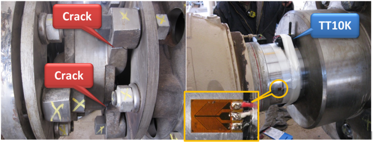
Figure 1
Peak torque of more than 450% of FLT was initially found with the compressor loaded, which is considered excessive even for reciprocating machinery. However, the signal appeared clipped (Figure 2) so the unit was shut down to adjust the transmitter. It is important to check the time wave forms for flat spots, spikes, drop-outs, etc. to ensure good data collection. After changing the transmitter gain, the unit was re-started and the maximum torque was actually 630% of FLT (1,400,000 / 222,000 = 6.3). Comparison with other measurements such as motor current and cylinder pressures verified correct horsepower and that the strain gage telemetry system was providing accurate readings. In addition, the built-in shunt calibration had been used during installation of the system to verify scaling.
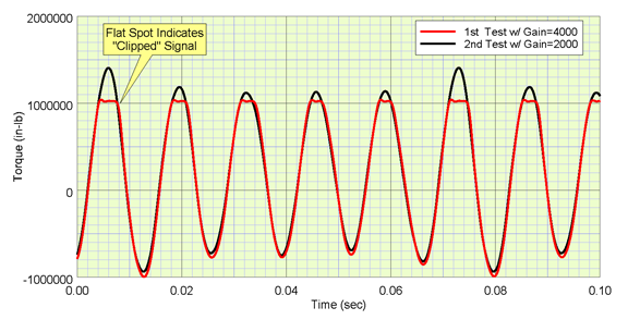
Figure 2
Analysis
The high torque measured in the coupling exceeded the manufacturer’s allowable limits and caused the failure. The first torsional natural frequency (TNF) was coincident with 5× running speed, which greatly amplified the dynamic torque (AF ≈ 80). For a reliable system, the TNF should have a separation margin (SM) from significant compressor harmonics. API recommends a SM of 10% when possible.
The system needed to be modified. The compressor manufacturer offers “detuners” or internal flywheels that can be bolted onto the crankshaft. This compressor frame could accommodate 3 detuners, which were promptly ordered from the factory and express shipped to the location.
Conclusion
The modified compressor unit was re-tested. Strain gage measurements confirmed that this additional inertia lowered the first TNF from 75 Hz to 71 Hz (now 5% below 5× running speed), greatly reducing the torque amplitude at that compressor harmonic.
With the detuners installed, the overall torque level in the coupling was acceptable. The before and after comparison is shown in Figure 3. Note that the other compressor harmonics did not change much in amplitude.
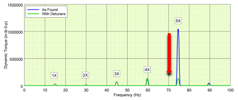
Figure 3